PROJECT
Electric Scooter wheelchair
Introduction
Prima di illustrare le varie fasi di montaggio vorrei innanzi tutto esprimere la mia sincera gratitudine al mio relatore Prof. Andrea Vitaletti per il continuo supporto della mia tesi e delle relative ricerche, per la sua pazienza, motivazione e conoscenza.Ringrazio, oltre al mio relatore, il Sig. Massimo di a.e.o srl per averci fornito una sedia a rotelle pieghevole in comodato d'uso. Senza il loro supporto non sarebbe stato possibile condurre questa ricerca.
In recent years there has been a rapid explosion in the spread of scooters, especially in cities and urban districts, by virtue of the fact that these allow benefits on several fronts: allowing for sustainable mobility while allowing easy access to the various areas of the city or points of interest.
So far the use of these means is only possible for people who do not have a serious disability therefore with this thesis work we intend to extend this possibility also to people with disabilities in particular by focusing on the mechanical integration between the scooter and the wheelchair and on adapting the control software of the scooter to a different type of load than common use.
Furthermore, since electric scooters do not have reverse gear at the level of the electric motor, it is necessary to ensure that this is still done even by those with disabilities. In this sense, the structure we built does not in any way interfere with the user's ability to reverse in the same way as he would do with a wheelchair not equipped with a scooter. Specifically, by acting on the rear wheels of the wheelchair and making the steering using the handlebar of the scooter, it is possible to reverse without any effort without the scooter being an obstacle in carrying out these actions.
First Assembly and Experimental Results
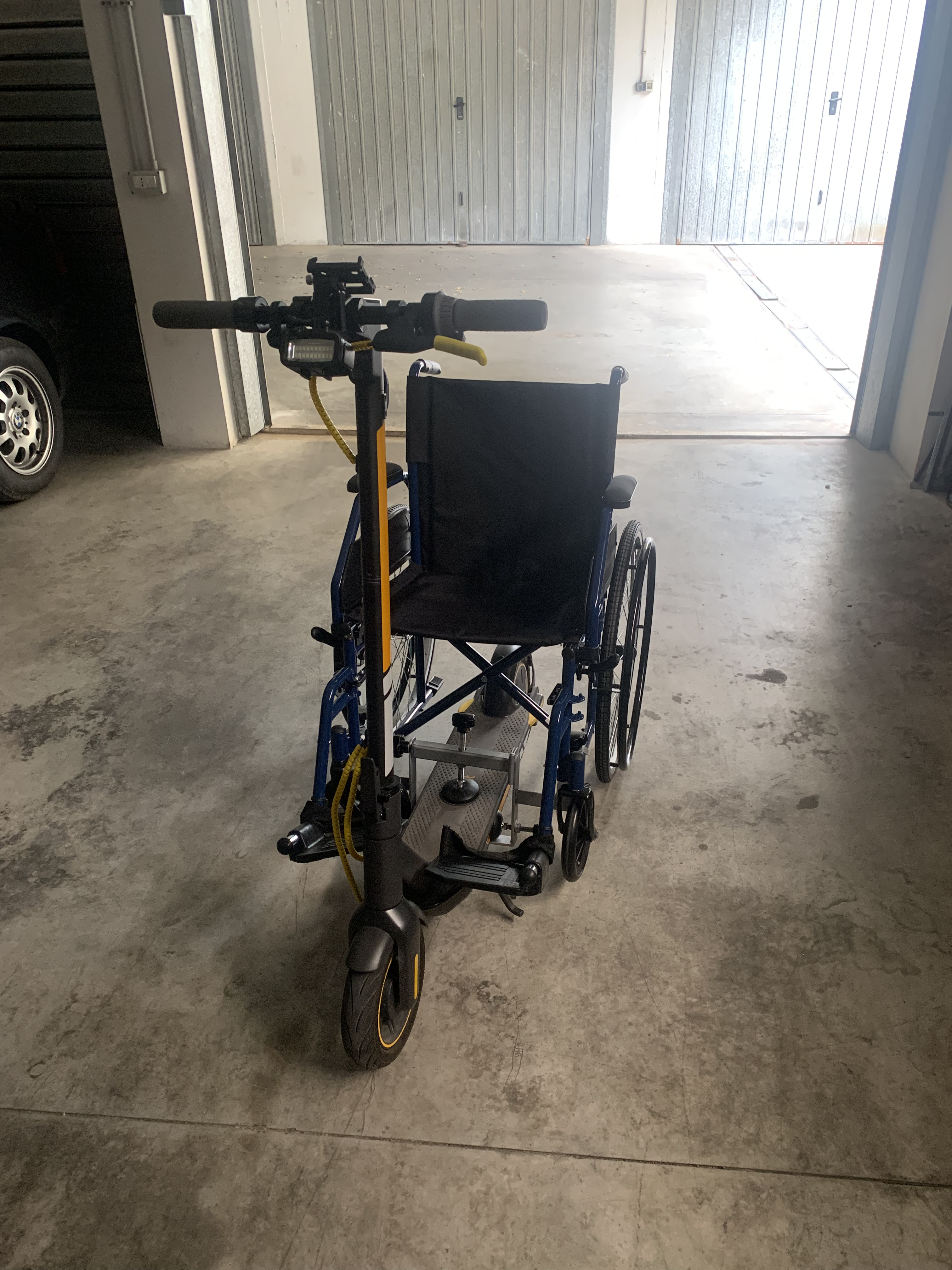
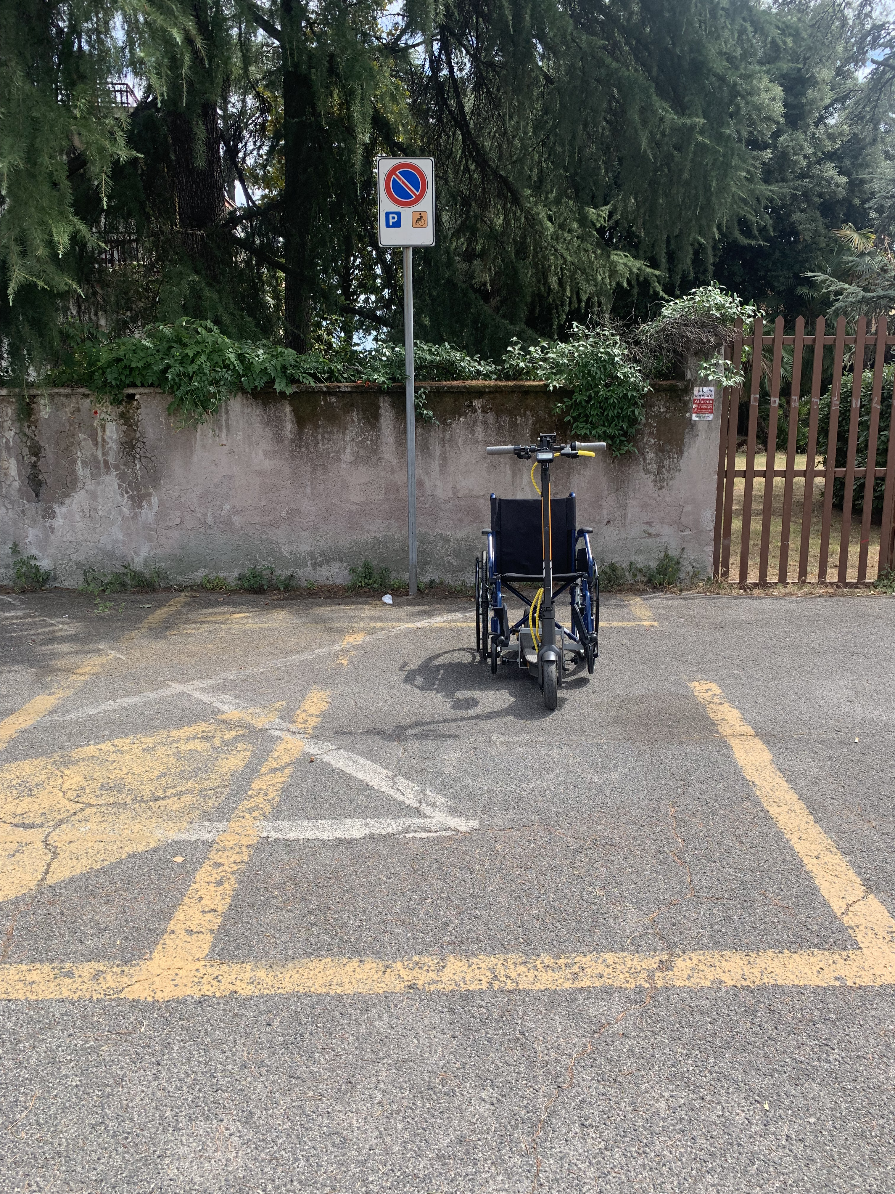
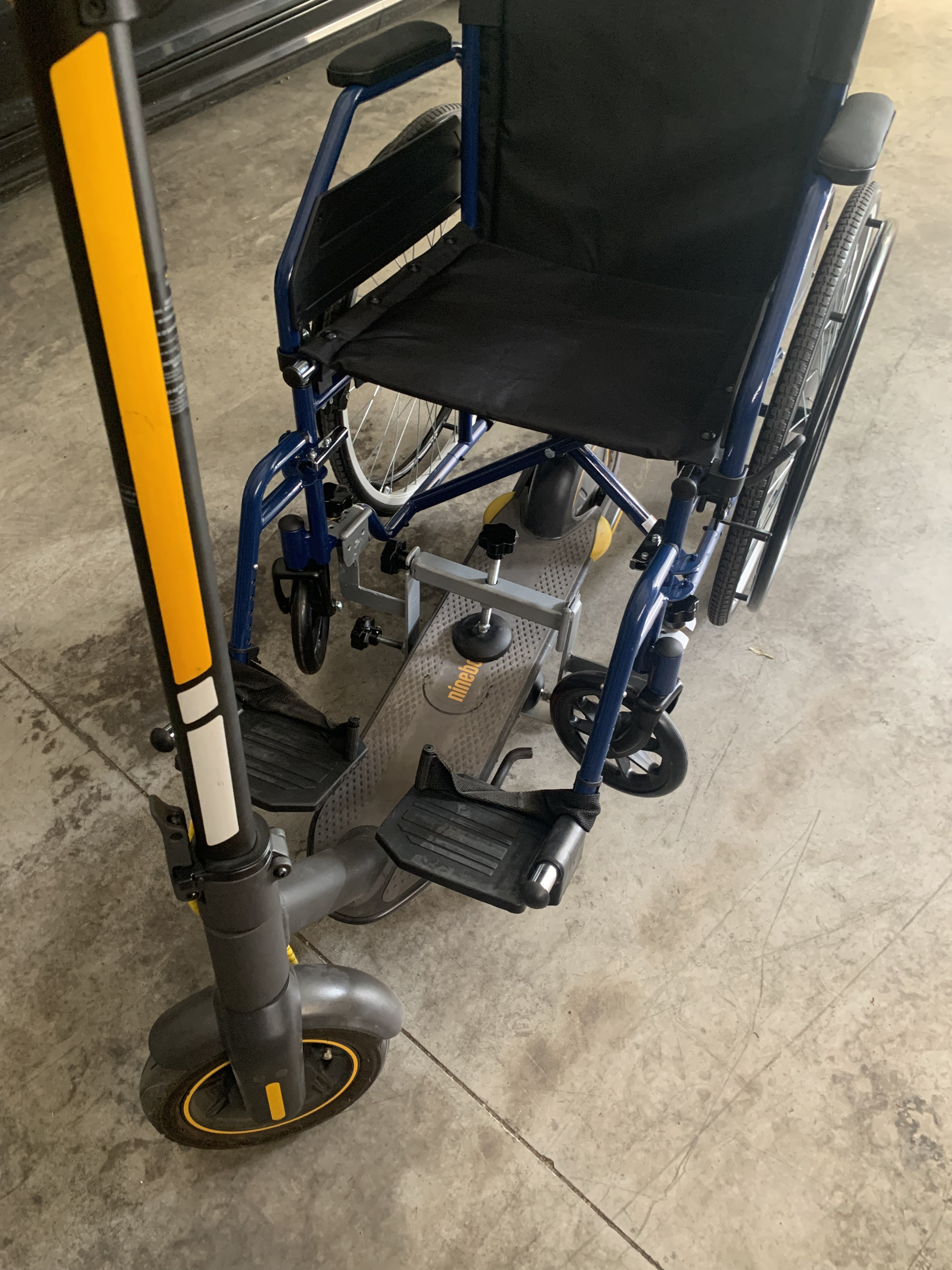
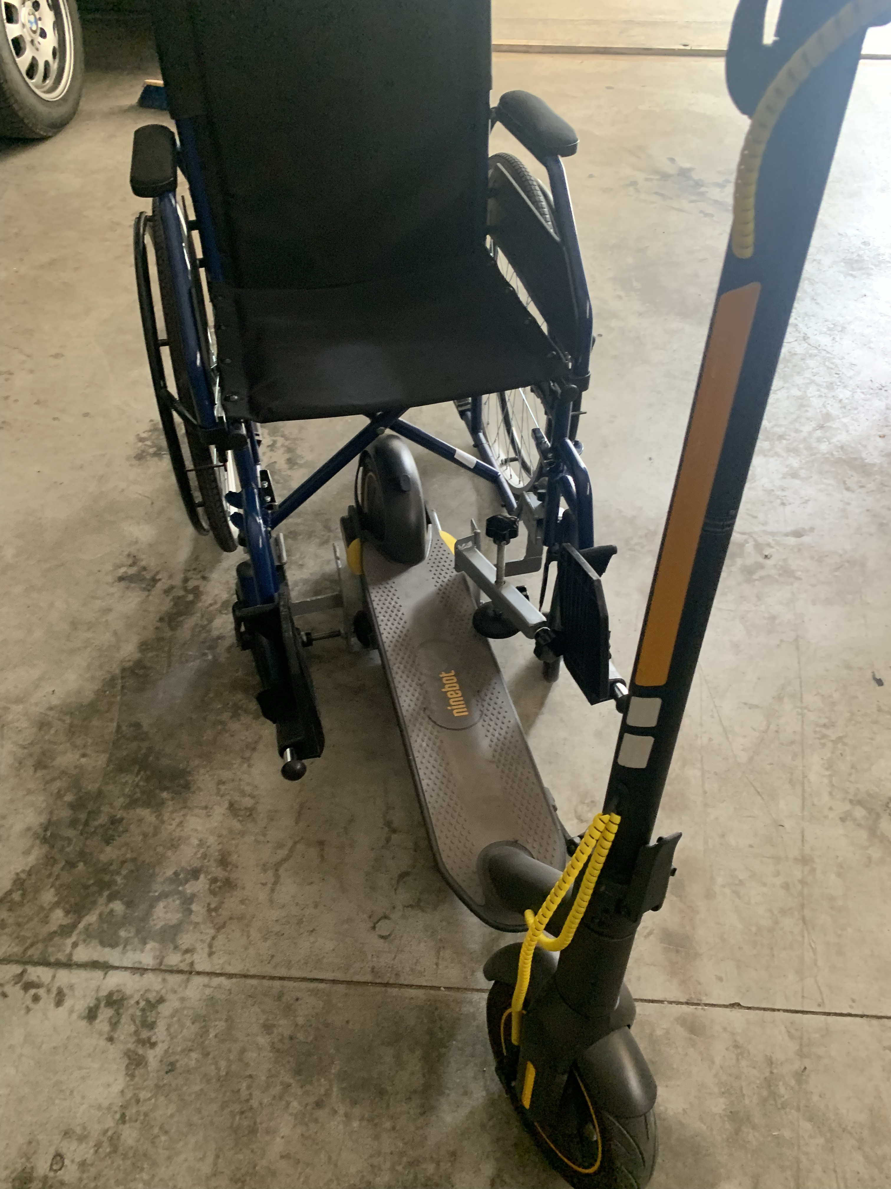
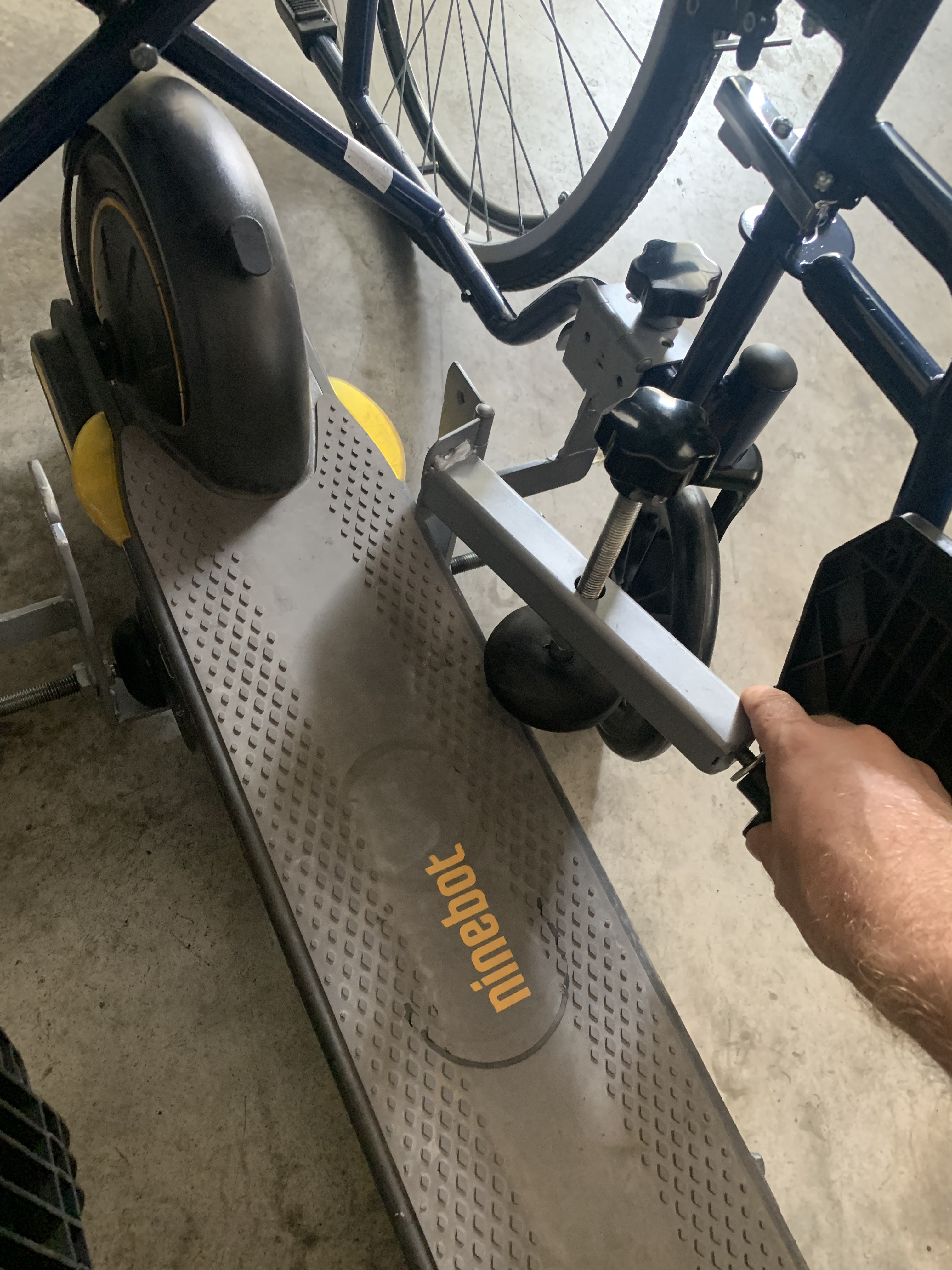
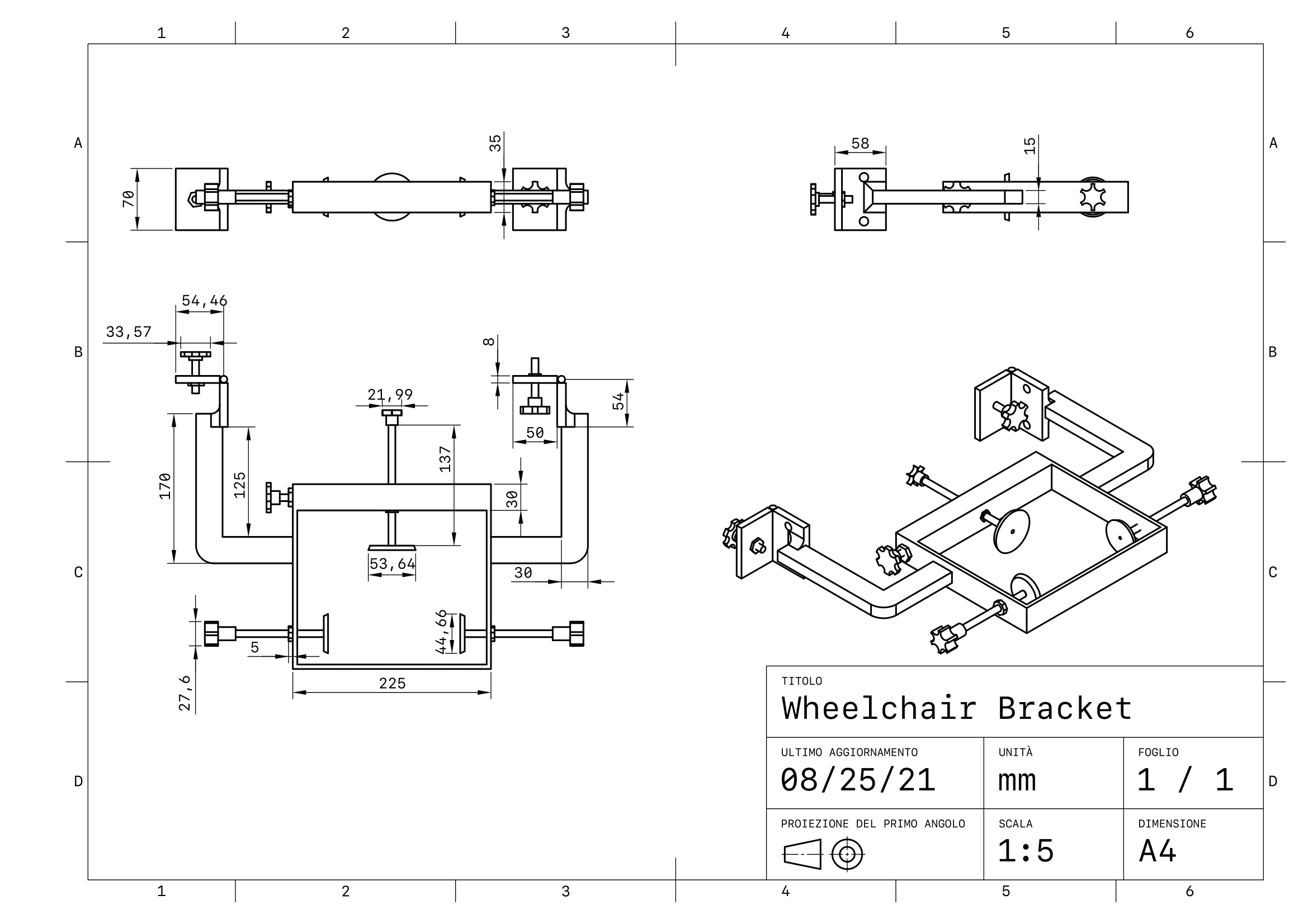
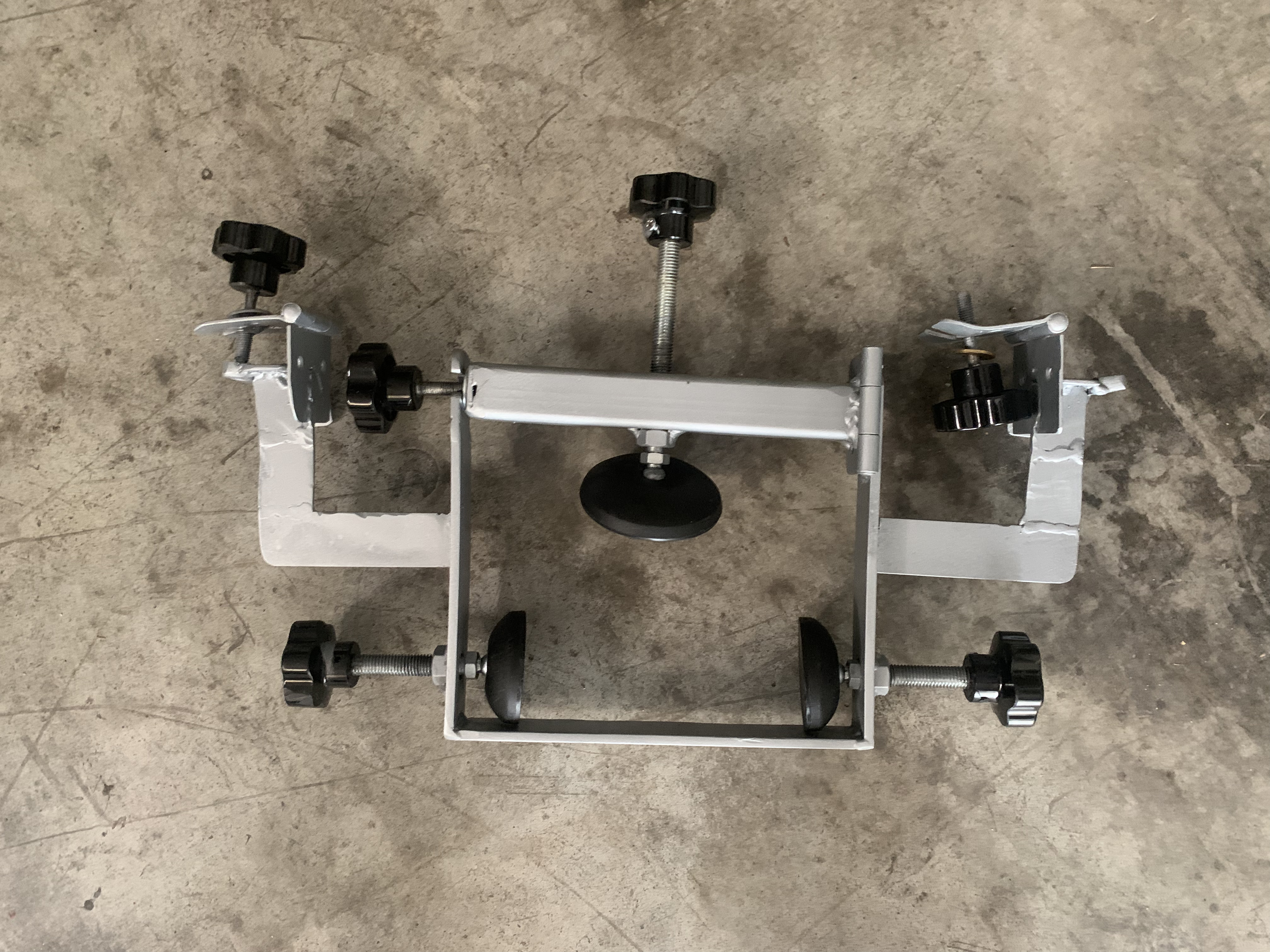
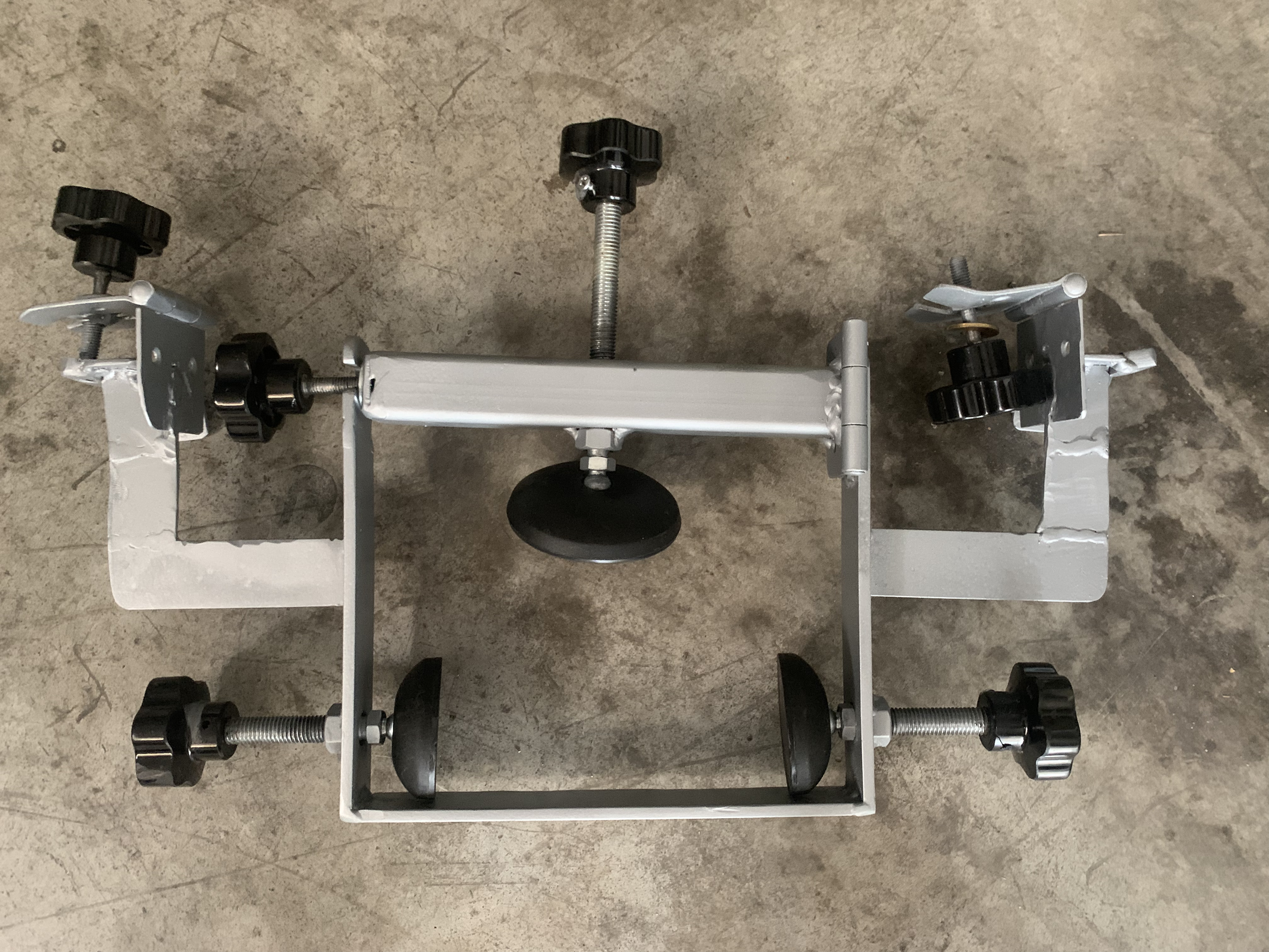
In this chapter we will show the various ways in which a mechanical coupling was made between the wheelchair and the electric scooter. Specifically, two main ways of interconnecting the parts have been identified, but each of them has advantages and disadvantages that we will also illustrate through photographs showing the type of assembly. In both cases the support that allows the connection between the two parts is the same so the use of one mode over another does not affect the components and is at the discretion of the end user. In particular, a support was created to be installed at the base of the wheelchair structure near the rear wheels, thus becoming an integral part of the wheelchair structure. A mobile component is added to this support which, by means of a knob, allows the scooter to be fixed to the aforementioned support.

Specifically, three knobs were used connected to three respective threaded rods and three 3D printed nylon anti-vibration pads. The threaded bars have been cut to size and, through a joint in the part that connects them to the vibration dampers, allows the scooter to be held firmly on the support with respect to the longitudinal and lateral movements produced by acceleration, braking and steering phenomena. Furthermore, the knob placed in a horizontal position with respect to the ground allows to raise the position of the front wheels of the wheelchair which, in both assembly modes, would create problems of a kinematic nature. In this sense they are "disabled" in their functionality and therefore the movement of the wheelchair will be subject only to the traction and steering imposed by the scooter. Furthermore, through a steel hinge, the mobile part connected to the support allows the scooter to enter under the wheelchair without it having to be lifted or moved. The images relating to the various parts of the joint and the components used will be shown below.
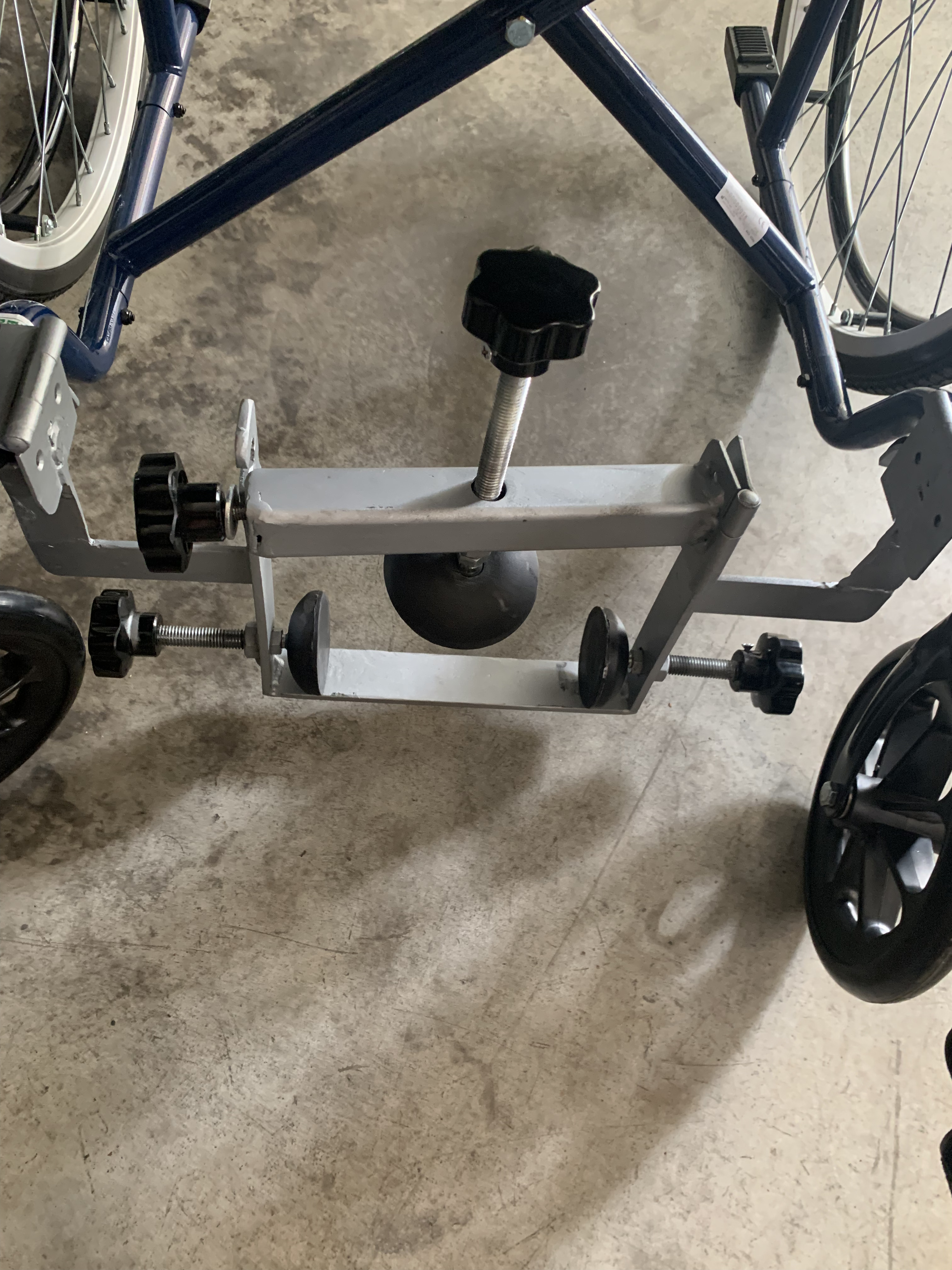
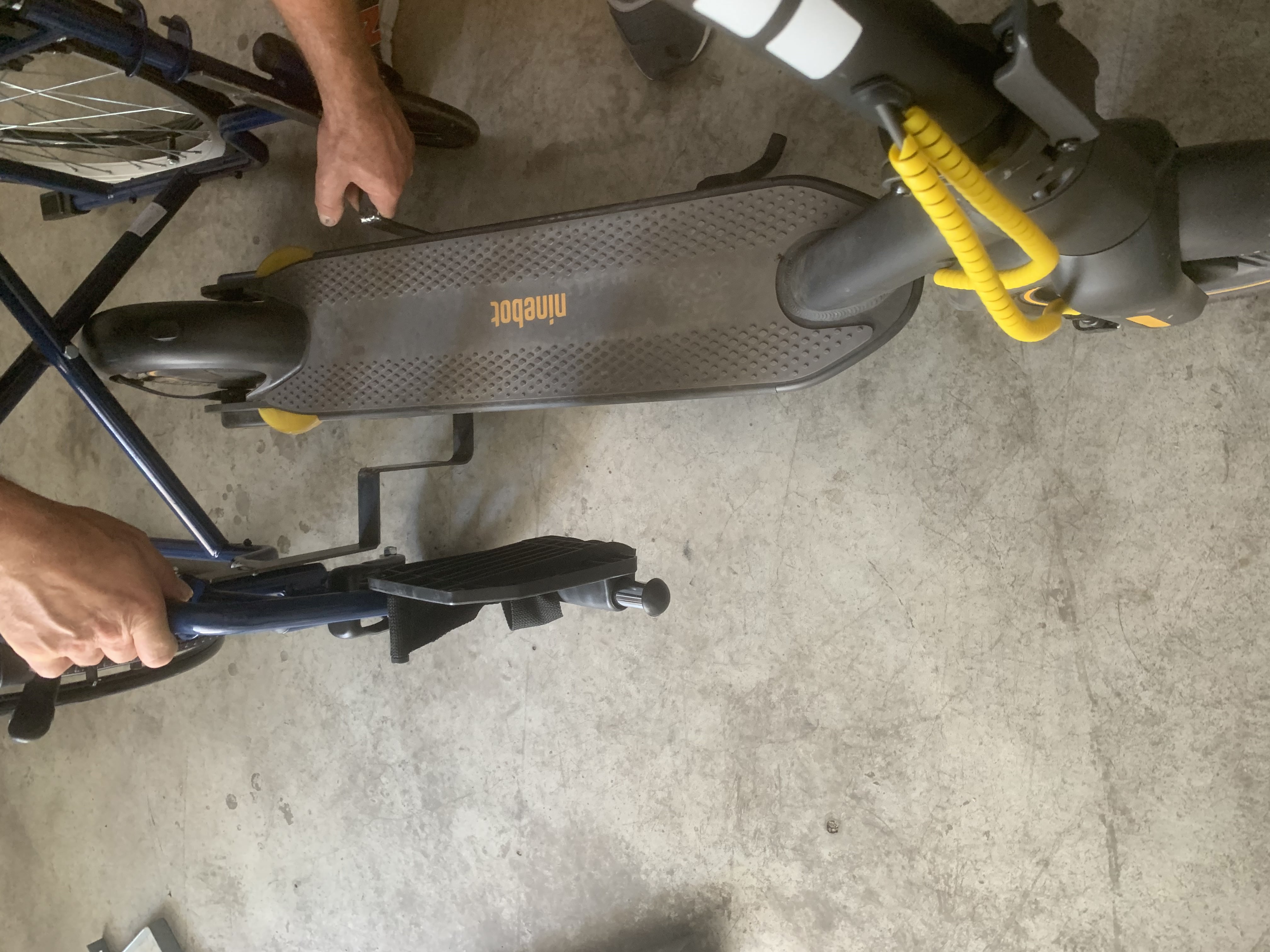
First assembly method
The first assembly method requires that the rear wheel of the scooter is located before the "x" structure, that is the one that allows the wheelchair to be folded. The use of this mode requires that the steering wheel of the scooter is folded because otherwise it would be too far from the seat of the wheelchair. In this sense, the use of the folded steering allows the user to enjoy a wide view and at the same time to carry out steering maneuvers easily and without fatigue. On the other hand, however, the turning radius is considerably reduced, i.e. by about 30% of the steering of the scooter, which effectively reduces the steering capacity of the scooter. In light of this problem, a further assembly method has therefore been envisaged, even if at the present stage of development this is the one that presents the most advantages. Some images related to this assembly method and its use will be shown below.
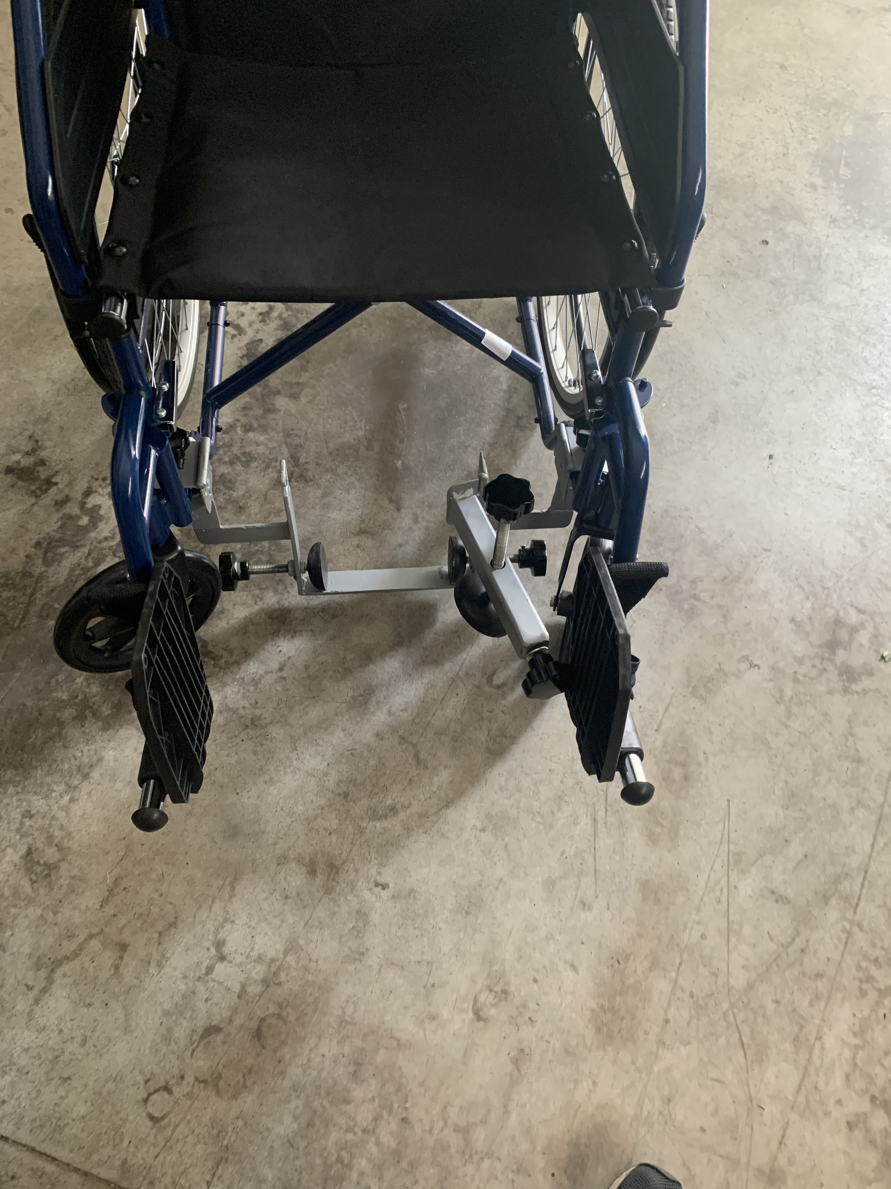
Second assembly method
The first assembly method requires that the rear wheel of the scooter is located before the "x" structure, that is the one that allows the wheelchair to be folded. The use of this mode requires that the steering wheel of the scooter is folded because otherwise it would be too far from the seat of the wheelchair. In this sense, the use of the folded steering allows the user to enjoy a wide view and at the same time to carry out steering maneuvers easily and without fatigue. On the other hand, however, the turning radius is considerably reduced, i.e. by about 30% of the steering of the scooter, which effectively reduces the steering capacity of the scooter. In light of this problem, a further assembly method has therefore been envisaged, even if at the present stage of development this is the one that presents the most advantages. Some images related to this assembly method and its use will be shown below.
Graphical Results
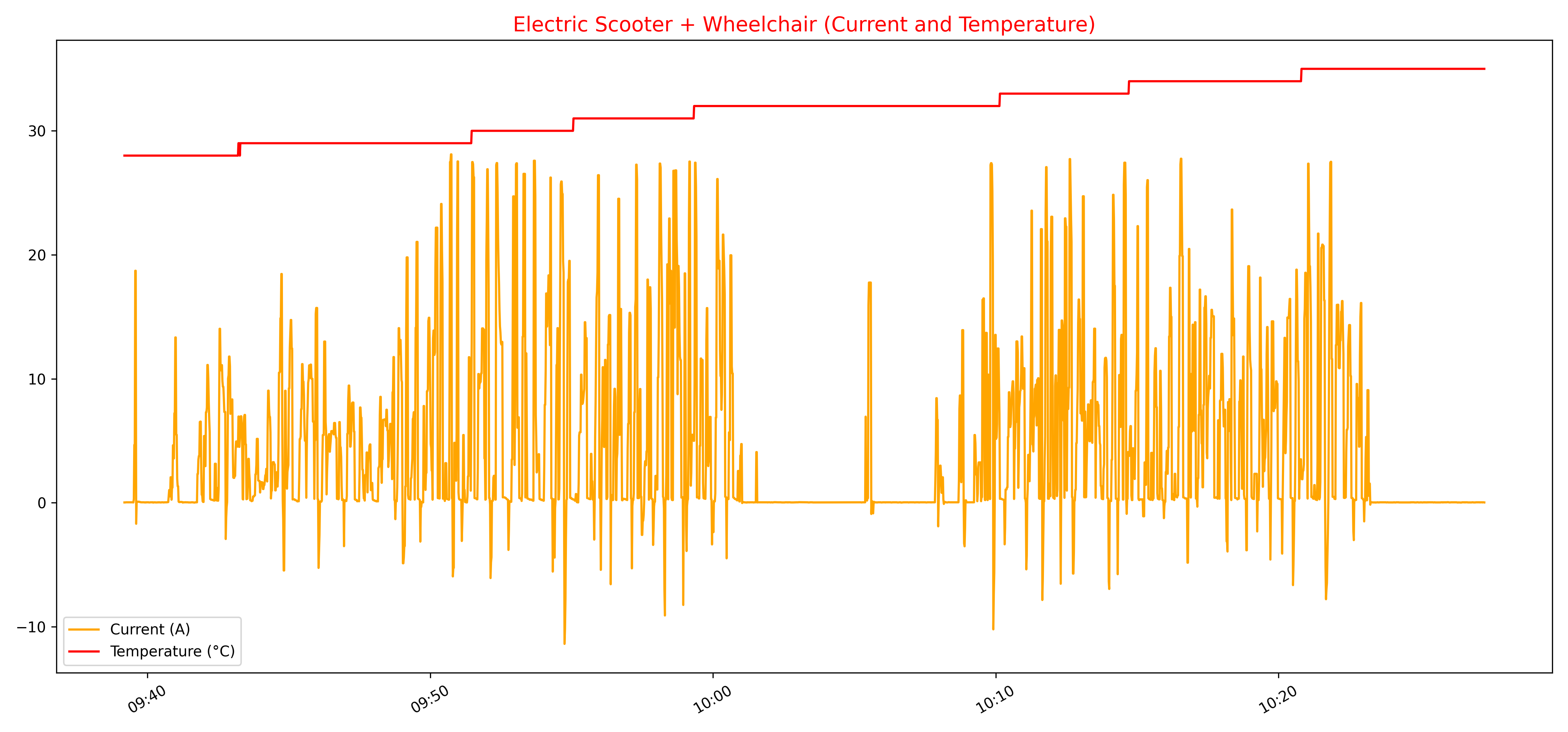
Below we will illustrate numerous graphs aimed at showing the performance of the scooter with the standard firmware, driven without a wheelchair, and with the custom firmware created in this thesis, coupled to the wheelchair. Specifically, the graphs relating to current, battery discharge, temperature, residual distance, voltage and power supplied by the motor will be shown.
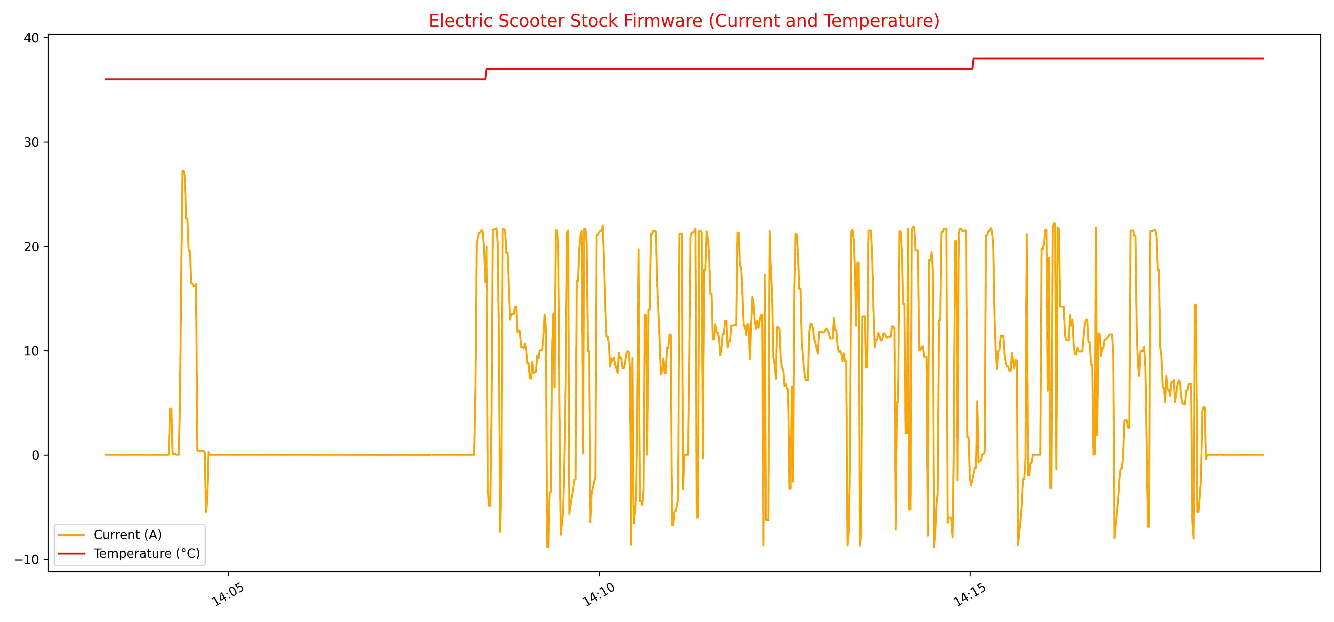
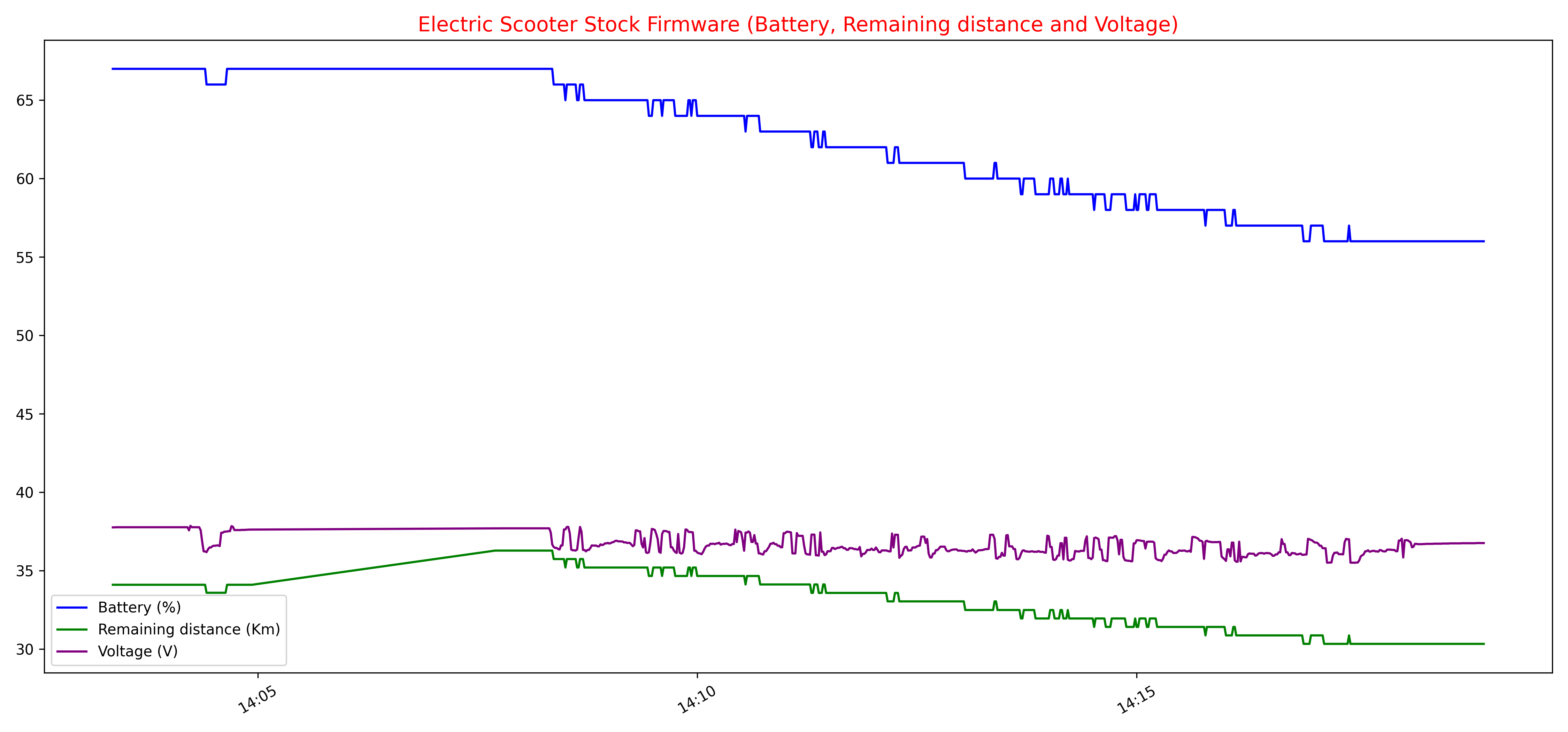
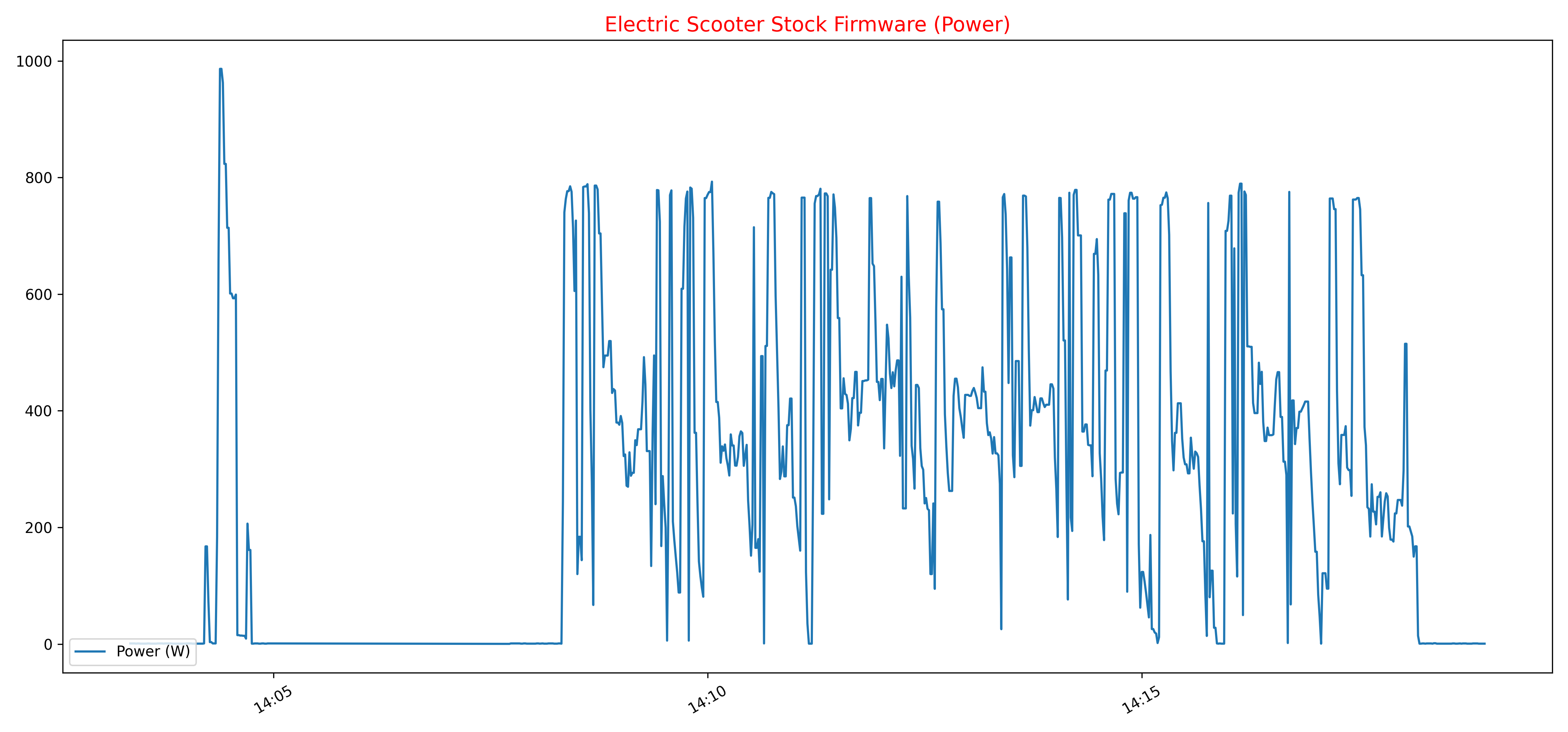
From this point on we will show the graphs relating to the physical quantities that it was possible to acquire regarding the operation of the electric scooter coupled to the wheelchair.

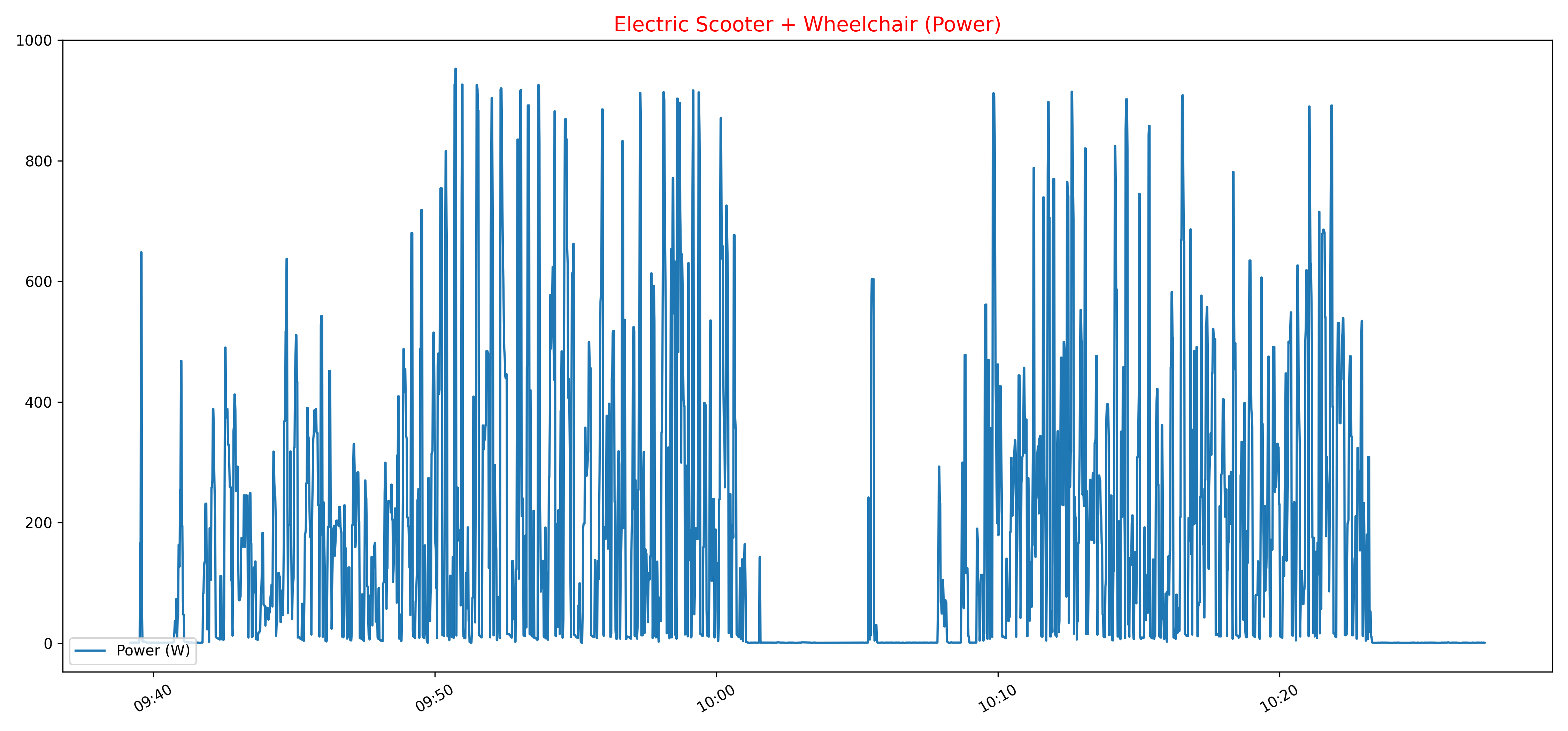
The graphs below show the test drive with the relative distance traveled during the road test.
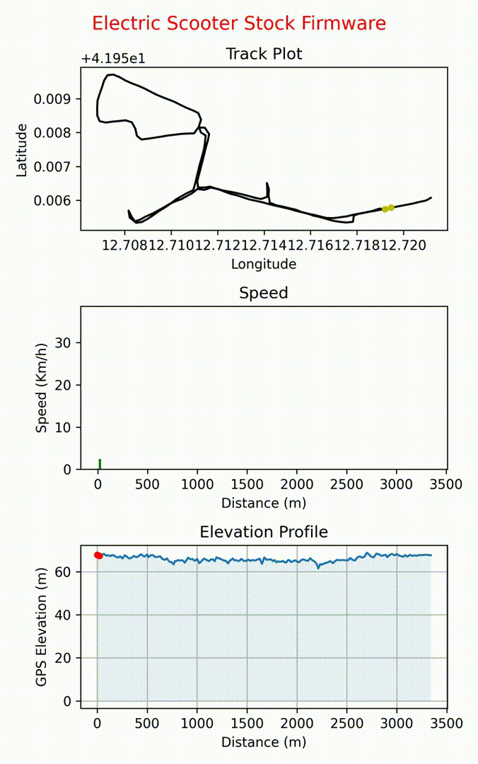
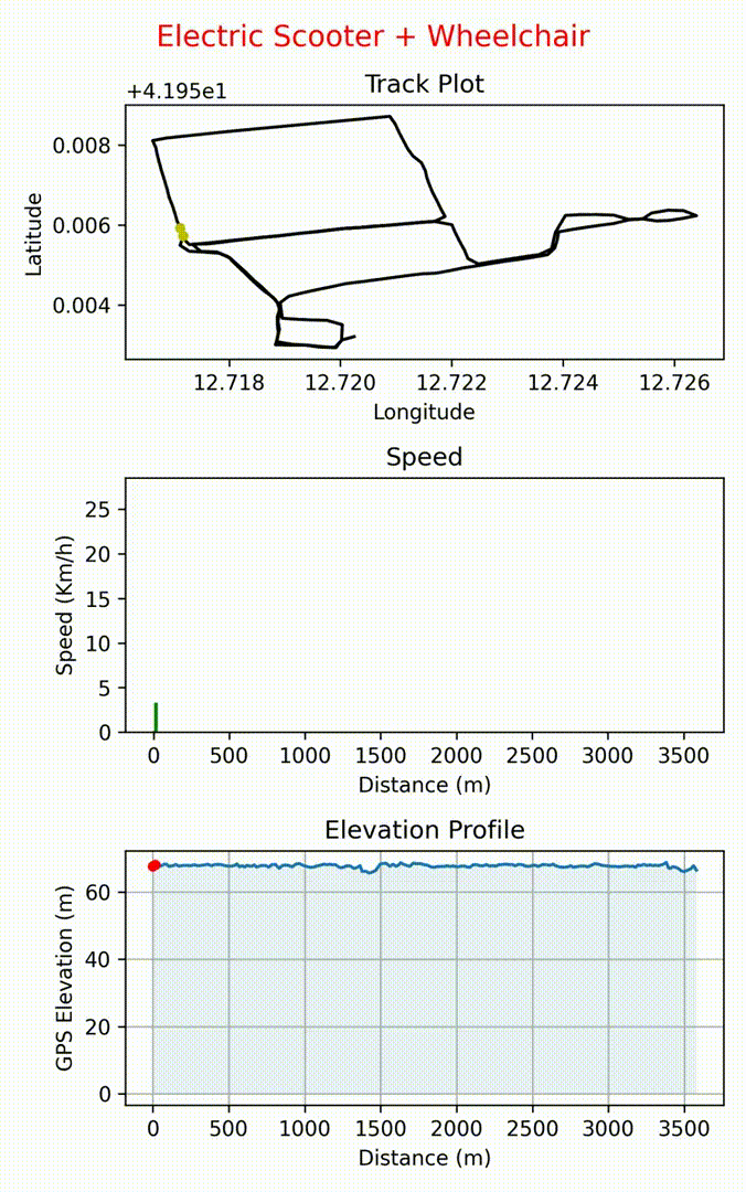
Distance traveled, speed and altitude
Conclusions and future work
The goal of this thesis was to produce a first working prototype that allows any wheelchair owner to take advantage of the additional possibilities and features offered by an electric scooter.
On the basis of the experiments carried out, encouraging results emerged as it was possible to achieve the mechanical coupling between the two bodies and the modification of the firmware without affecting the functioning of the electric scooter and without adding further problems for the user. Furthermore, it was possible to achieve this without having to distort the structure and nature of the scooter and wheelchair, in such a way as to guarantee their operation regardless of the connection between the two.
On the other hand, less encouraging results also emerged from the experiments since, as shown in the chapter on assembly methods, both do not allow to have a 100% efficient and effective guide since both modes have advantages and limitations due to the structure. physics of the two so heterogeneous media. In particular, the main flaw relating to reduced visibility would be dealt with when there are electric scooters with telescopic steering on the market which, however, are currently of very little diffusion and in any case a modification of the steering would require a significant adaptation work. This problem would therefore not allow the use of sharing scooters. On the other hand, the second mode would allow the scooter to be used by both able-bodied and disabled users, but at the expense of a reduced turning radius when using a wheelchair. We therefore believe that this second mode is the most suitable to be used on a permanent basis and that allows access to the benefits and potential of the scooter to the widest possible audience.
However, there is still a lot of work to be done as this project could be extended to a larger number of brands of electric scooters and wheelchairs and also companies operating in the electric scooter rental market could be involved in order to share with them the results obtained in this thesis work thus allowing disabled people to be able to use the modified firmware on the basis of their needs, with a simple request to the server via an application.
Further developments could be aimed at obtaining a finer tuning of the firmware parameters and therefore more effective and comfortable for driving by people with disabilities, also adapting it to the various engine models available on the market. Further room for improvement can be had by integrating cutting-edge technologies in this project, for example through the use of machine learning for computer vision tasks. More specifically, video cameras could be integrated into the scooter and then used to be able to have a representation of the outside world and on the basis of this guarantee greater safety through the aid of machine learning algorithms, for example in helping the user to carry out the braking phase when an obstacle or a red light is detected.
In closing, further developments that have already been foreseen concern for example the possibility of installing a safety belt on the wheelchair, an increased battery that allows you to extend the autonomy of the scooter and a reinforcement of the scooter control unit that allows for greater performance. and faster engine reaction times.
The reinforcement of the control unit consists in adding tin and possibly a copper wire in the rear tracks of the control unit itself, where high levels of current pass through. In this way there will be an increase in the diameter of the same which will allow not to have overheating. A broader and more advanced work can include the replacement of mosfets with higher quality components without causing any damage to the control unit with firmware that use higher currents.
More photos and videos